Hey guys, if you’ve ever had to source metal stamping parts for a product—whether it’s a car component, a kitchen appliance, or even a tiny electronic bracket—you know how frustrating it can be when a part works for a minute, then bends, cracks, or just can’t keep up with the job. I’ve been in the metal stamping game for over 10 years now, running a shop that makes custom stamped parts for all kinds of industries, and let me tell you: half the time, the problems aren’t with the stamping process itself—they’re in the original design. A lot of designers (even some super experienced ones) draft up a part without thinking through how metal will actually behave when you punch, bend, or form it. The good news? Optimizing that design for stamping doesn’t have to be rocket science, and it can make your parts way more reliable, cut down on waste, and save you cash in the long run. Today I’m breaking down the key stuff I preach to every client that walks through my door—no fancy jargon, just real-world tips that work. Metal Stamping Parts
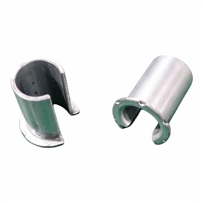
First off, let’s talk about one of the biggest mistakes I see: ignoring material behavior when designing bends. I can’t tell you how many times a designer will draw a sharp 90-degree bend without considering the metal’s grain direction. Most metals—steel, aluminum, brass—have a “grain” from how they’re rolled at the mill, like the grain in wood. Bend a part with the grain, it’s way more likely to crack; bend it across the grain, it bends smooth and strong. I once had a client come to me freaking out because their metal brackets were cracking right after they put them into a car assembly line. They’d drawn the bend parallel to the grain, and the thin 2mm steel they were using just couldn’t handle the tension. We adjusted the bend direction so it ran perpendicular to the grain, and the crack rate dropped from 12% to almost zero. Another thing with bends: the minimum bend radius. Every metal has a sweet spot. For soft steel, that’s like half the material thickness; for harder alloy steel, it’s closer to the full thickness. If you make the bend radius too tight, you’ll get fractures, weak spots, or even parts that don’t fit together right. I always tell clients to err on the side of a slightly larger radius than they think they need—you can always trim it down later, but you can’t fix a cracked part. Also, add some relief holes or notches near bends if they’re close to edges. If you have a bend right next to a square cut, the metal will stretch unevenly and crack at the corner. A tiny 3mm notch fixes that every time. I had a client making electric motor brackets that had bends within 5mm of a cut edge—they were tossing 1 in 5 parts. We added those relief notches, and suddenly their yield went up 20%. That’s the kind of quick win we’re talking about.
Next up, hole placement and size. This is another area where designs go sideways fast. A lot of designers drill holes (or stamp them, obviously) wherever they need them, without checking the distance from holes to edges or to other bends. If a hole is too close to an edge, when you stamp it, the metal around the hole will stretch, causing the edge to curl or the hole to deform. The general rule here is: the distance from a hole’s center to the edge should be at least twice the hole’s diameter. If you have two holes next to each other, their centers need to be at least three times the larger hole’s diameter apart. I once worked with a startup making custom laptop hinges. They’d put two 4mm holes 8mm apart (so centers 8mm, which is only 2x the diameter) to mount the hinge arms. When we stamped them, a bunch of holes got oval-shaped, so the screws wouldn’t line up. We widened the space between holes to 12mm (3x the diameter) and fixed the alignment issue. Also, avoid holes too close to bends. The distance from a bend line to a hole’s center should be at least 1.5 times the material thickness. If a hole is 5mm from a bend line in 2mm thick steel, when you bend it, the metal will warp the hole, making it too small or misaligned. We’ve had parts that failed inspection because of this—fixing that distance is a super easy design tweak that prevents rework.
Then there’s part symmetry and uniformity. As a stamping supplier, I hate when I get a design that’s all lopsided, with super thin sections here and thick ones there, or a part that’s way bigger on one end than the other. Irregular shapes or uneven thicknesses cause uneven material flow during stamping. When you run metal through a stamping press, it has to move smoothly into the die; if one side is way bigger or has a sharp angle, it can bunch up, creating wrinkles, or stretch too thin, creating weak points. For example, if you’re stamping a bracket that has a curved end on one side and a straight end on the other, make sure the curve isn’t super extreme that it forces the metal to stretch more than it can handle. Also, keep wall thickness consistent across the part as much as possible. I had a client making decorative metal tags for jewelry—they designed tags with sections 0.8mm thick and other sections 1.5mm thick right next to each other. When we stamped them, the thinner sections would tear during the blanking step, and the thicker ones didn’t form right. We simplified the design to a uniform 1mm thickness, and the part quality went through the roof. If you need a part to be stronger in one area, don’t make the whole section thicker—use a reinforcing rib instead. Ribs are thin, raised lines in the metal that add stiffness without increasing the overall material thickness, which makes stamping way easier. Ribs can also cut down on material waste, since you don’t have to use extra thick metal for the whole part.
Material selection is tied straight to design too, and this is something I see designers sleep on all the time. They’ll pick the cheapest metal they can find without thinking about the stamping process or the part’s end use. For example, if you’re making a part that needs to hold up to a lot of vibration, hard steel is better than soft steel—soft steel bends too easy. But if you’re making a tiny electronic bracket that only needs to hold a wire in place, soft aluminum is lighter and easier to stamp, so why use heavy steel? Another thing about materials: work hardening. Some metals, like copper or certain stainless steels, get harder when you bend or form them. That’s actually a good thing, but you have to account for it in the design. If you’re making a part that needs to be bent multiple times, the work hardening might make the metal too brittle and crack, so you need to include an annealing step after forming, or pick a more ductile metal. I had a client making stainless steel brackets for outdoor signs—they used 301 stainless, which work hardens a lot. When they bent the part twice to get the right shape, it cracked. We suggested 304 stainless, which is more ductile, and adjusted the bend radii to accommodate the material’s flexibility, and the parts lasted way longer than their previous ones. Also, if you’re plating or finishing the part later, make sure the metal you pick is compatible. Some metals don’t plate well, which means you’ll get wasted parts from the finishing process, so that’s something to bring up with your stamping supplier early on—don’t wait until you have 1000 parts stamped and find out they can’t be painted or coated.
Now, let’s talk about avoiding undercuts and complex features where you can. I know, sometimes you need a part with a little groove or a notch that goes inward, which is called an undercut. The problem with undercuts is that they require extra tooling, which makes the stamping process more expensive, and also weakens the part. Plus, not all stamping presses can handle undercuts, so you might have to do secondary operations, which add time and cost. I always tell clients to ask: do I really need this undercut, or can I redesign it to be a simple, straight feature? For example, if you need a small slot that runs along the side of a bracket, instead of a curved slot that cuts inward, a straight slot is way easier to stamp, and stronger too. Another thing: if your part has a feature that has to be a certain size within 0.1mm, that’s called a tight tolerance. Tight tolerances sound good in theory, but every time you tighten the tolerance, you make the stamping process more expensive. It requires more precise tooling, slower press speeds, more inspection, and higher rates of scrap. Ask yourself: do you really need a 0.1mm tolerance, or would 0.2mm work for your product? For most parts, 0.2mm is more than enough, and it cuts your production cost by 15-20% easy. I had a client making parts for a home appliance—they had a tolerance of 0.05mm, which was totally unnecessary. We adjusted it to 0.2mm, and our production time per part went down, scrap went way down, and their total cost was $0.30 per part instead of $0.45. That adds up when you’re ordering 50,000 parts a month.
Wait, let’s not forget about draft angles. If your stamped part is going to be ejected from the stamping die, you need draft angles on all vertical surfaces. Draft is a slight taper, like the side of a pyramid, so the metal doesn’t get stuck in the die. No draft angle means you have to force the part out, which can bend or scratch it, or even damage the die. The draft angle doesn’t have to be big—1 to 2 degrees is enough for most metals. If you miss this, you’ll have parts that get stuck in the press every few cycles, leading to downtime and broken parts. I once had a client that forgot draft angles on a stack of small metal cups we were stamping. We had to modify the dies in between runs, which delayed their order by a week and cost them extra. Easy fix, easy mistake to make.
Another big one: think about secondary operations before you finalize the design. A lot of designers assume all parts are done as soon as they come out of the stamping press, but most parts need something else—deburring, plating, painting, tapping holes for screws, bending again. If you design a part with sharp, burr-heavy edges and you’re going to deburr it, leave enough material for that step so you don’t reduce the part’s strength below what you need. For example, if you have a 2mm thick edge, and deburring will remove 0.1mm, start with a 2.1mm edge so you still have 2mm left after deburring. If you design the edge to be exactly 2mm and deburr it, you’ll have a weak, thin edge that could break. Also, if you need to tap a hole after stamping, make the hole size a little larger than the standard tapping size to account for any minor misalignment from the stamping process. I had a client that kept breaking taps in their parts because they designed the hole too small—we adjusted the hole size, and tap breakage went down to almost nothing.
Let’s wrap this up with a quick example of how this all comes together. Last quarter, I had a client that was making mounting brackets for a fleet of electric bikes. Their original design had sharp bends parallel to the grain, holes too close to edges, tight tolerances that weren’t needed, and a hard steel that was prone to cracking. The first order had a 18% scrap rate, delays, and they were going over budget. We tweaked the design: changed bend direction to cross the grain, used a soft ductile steel, adjusted hole placement to follow the edge distance rules, relaxed tolerances from 0.05mm to 0.2mm, and added relief notches near the bends. The scrap rate dropped to 2%, delivery time went up 2 days instead of 5, and their total part cost was 22% lower than before. That’s the power of design optimization—small tweaks, big results.
At the end of the day, metal stamping is all about working with the metal, not against it. Your design is the foundation, and if you get the design right, the stamping process will be faster, cheaper, and the parts will be stronger and more reliable. If you’re working on a new project, or having issues with your current stamped parts, don’t hesitate to reach out to your stamping supplier early—before you finalize your design. We can give you feedback on material selection, bend directions, hole placement, all that stuff, which saves you a ton of time and money down the line. I get it, designers have a lot on their plate, and it’s easy to overlook these small details, but that’s what we’re here for. We’ve seen thousands of parts, we know what works and what doesn’t, and we want your project to succeed as much as you do.
If you’re looking to optimize your metal stamping parts for better performance, lower costs, or higher yield, get in touch with our team to chat through your project. We’re here to help you refine your design so it works as well as it should.
Metal Stamping Dies References
- Groover, M. P. (2020). Fundamentals of Modern Manufacturing: Materials, Processes, and Systems (7th ed.). Wiley.
- Campbell, J. S. (2018). Metal Stamping Design and Process Optimization. Industrial Press Inc.
- Dieter, G. E. (1986). Mechanical Metallurgy (3rd ed.). McGraw-Hill.
- Tschachler, H. (2021). Practical Guide to Metal Stamping Dies and Processes. SME.
- Kalpakjian, S., & Schmid, S. R. (2020). Manufacturing Processes for Engineering Materials (8th ed.). Pearson.
Dongguan Changdong Tool & Die Co., Ltd.
With abundant experience, we are one of the most reliable metal stamping parts manufacturers and suppliers in China. Please feel free to buy advanced metal stamping parts made in China here from our factory. Good service and quality products are available.
Address: No. 56-B, Fumin South Road, Dalang Town, Dongguan City, Guangdong Province, China
E-mail: sales@stamping-die.com
WebSite: https://www.metalstampingdie.com/
